Refurbishing a Linear Amp (Part One)
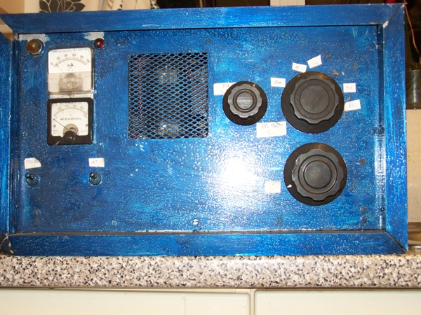 This is a series of articles doing a step by step refurbishment on an old homebrew HF linear amplifier. It has to be taken into consideration that when the Linear Amp was built everything at that time would be valves which were more forgiving unlike the transistors of today. The amp was 2 X RCA813 valves wired in grounded grid configuration and the input was fed directly to the cathodes of the valves with no matching network. (this was common in the old valve days)
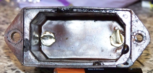
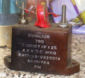 The first step was a visual examination of the linear and I was suspicious about the wax on the chassis below the plate blocking capacitor and the coating of the other capacitor wired in parallel on top of it had also melted. I removed the blocking capacitor and found that it had completely burned out, I would have to replace this with a suitable door knob capacitor.
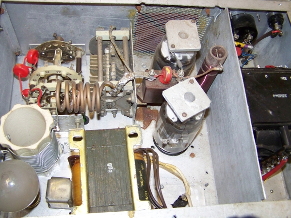 The large 10v filament transformer shown in the picture above is not suitable for the linear as it is not center tapped and will cause a 50hz modulation to the output, so this must be replaced with a proper 10v center tapped filament transformer. The filament transformers are hard to find, but I have a suitable transformer that I have rewound so the original one will be replaced by my homebrew one.
The 15 watt bulb on the left of the picture above was used as a soft start for the power supply and was in circuit when the linear was initially switched on (the 813 valves did not need the time for heating up as other valves do before HT was applied) when the HT switch was turned on it shorted out the bulb for full power to the HT transformer. This was going to be replaced by a proper soft start relay so that the HT switch would be completely separate from the main switch.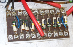
A 200 ohm potentiometer at the back of the linear was completely burned out and with some unconnected components and wires and two diodes on the rectifier board were shorted out with a piece of wire.I never gave this a second thought, the whole thing was going to be replaced with new components.
Because I was changing the filament transformer this meant that I had to also change the metering circuits, I decided that rather than a refurbishment, for safety this was going to be a major rebuild. I was also not happy with the cooling system on the Linear so I was going to change the layout of the fan’s for better ventilation.
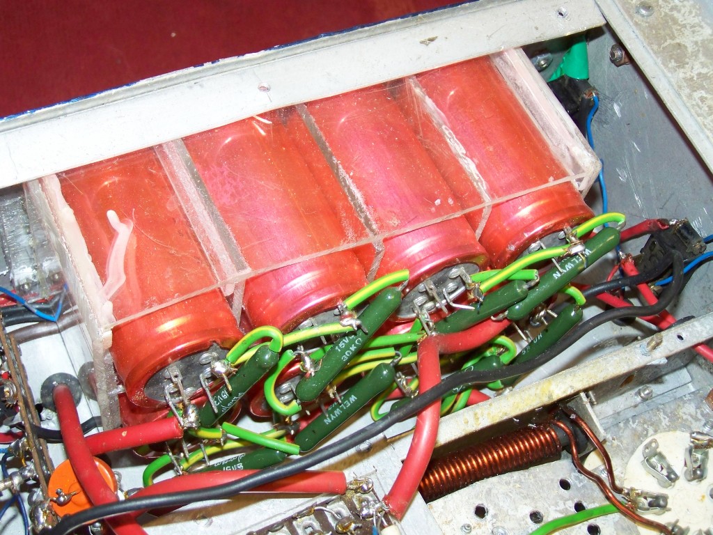 Turning my attention to the electrolytic capacitors on the power supply, visually they seemed OK and the bleeder resistors across the capacitors were all wire-wound and looked OK. The next stage was to make a new diode chain as I did not like the old one and try to re-form the capacitors and check them to see if they were all alright, I would use a variac transformer so I could slowly increase the voltage across them.
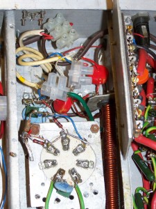 I did not like the wiring on the valve bases so decided to cut all this out and rewire the valve bases and make sure that they had a good earth as I was not happy with this part of the build. I removed all those components and the valve bases and while everything was disconnected it would be a good time to alter the chassis to improve the air flow round the valves.
My final check before starting anything was to check the aerial switchover relay and this proved to have been arcing so a new relay would have to be fitted.
I had set my stall out on what needed doing, all I had to do now was find the time to do it. Time to buy the XYL some flowers and a big box of chocolates so I could work on rebuilding the Linear Amp.
>>>Part Two

Comments
Refurbishing a Linear Amp (Part One) — No Comments
HTML tags allowed in your comment: <a href="" title=""> <abbr title=""> <acronym title=""> <b> <blockquote cite=""> <cite> <code> <del datetime=""> <em> <i> <q cite=""> <s> <strike> <strong>