Refurbishing a Linear Amp (Part Two)
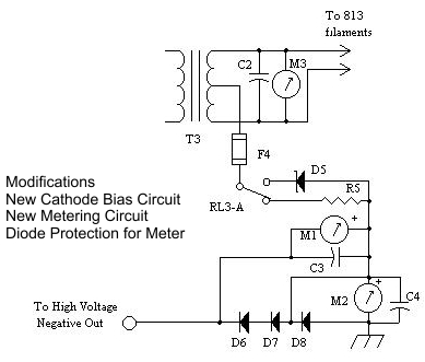
 Refurbishing the Linear Amp was still in progress, and because I was changing the old filament transformer for a proper center tapped transformer suitable for the amplifier, I had to change the circuit to take this into account.
Another modification to the amplifier was the cathode bias circuit as the old circuit did not have one. R5 is a 50K 10 Watt resistor that biases the valve at cut of when not transmitting keeping the valves cooler and D5 is a 5 volt 10 Watt Zener Diode which biases the valve for transmission.
For those not familiar with the grounded grid configuration D5 and R5 raise the voltage of the cathode above earth making the grids negative in respect to the cathode. on large transmitting valves, the heater filaments and the cathode are connected so share the same circuits.
D6 – D8 1N5400 3A glitch protection diodes for the meters in case of a negative going High voltage spike. F4 a high voltage 1A fast blow fuse provides further protection in the event of a catastrophic failure. All capacitors are .01uF @ 1000 volts and M1 = 1 amp meter and M2 = 50mA meter
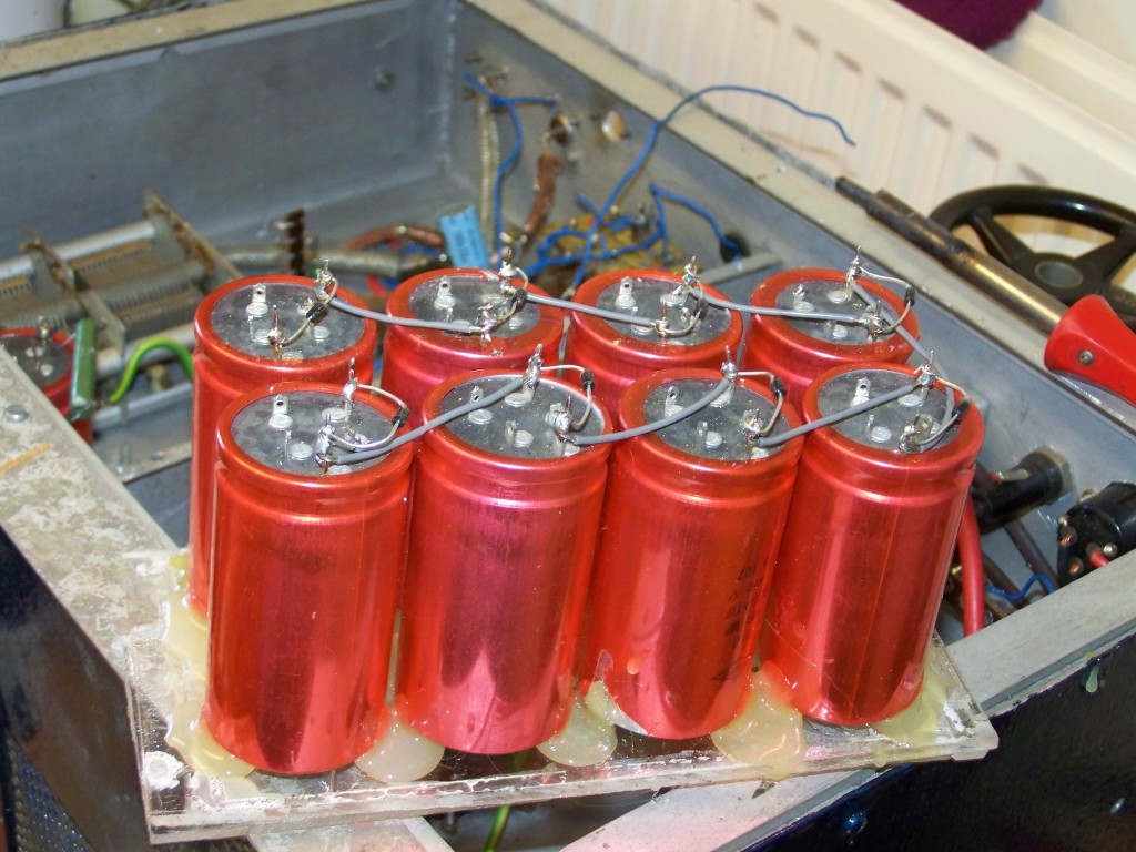
It was time to check the capacitor bank and I removed it from the Linear Amp and checked each capacitor individually for shorting / OC, I found two resistors were open circuit and there were no protection diodes across the individual capacitors so I decided to strip the bank down and replace all the resistors and add protection diodes. At the same time I hot glued the capacitors to the original perspex in way that the air flow could go round them everything was completed on the capacitor bank apart from the bleed resistors which had to be re-calculated.
This is where the health warning needs to be placed. Warning: Extreme Caution, Lethal Voltages, High Voltage WILL KILL I checked the HT transformer and found this to be OK with an output of 1.2KV which will give about 3KV with no load on the voltage doubler. Good wire wound resistors are hard to find so I recalculated the the bleed resistors for 2 watts and needed 562.5k resistance so I ordered some 680k 2watt metal film resistors as they would do the trick though the discharge time of the capacitors would be a lot longer.
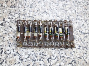
 I clipped the diodes from the diode chain and replaced them with 3A 1000piv diodes, but before this I checked the balance resistors which proved withing tolerance so this was another job done and ready to fit.
While I waited for the parts I had ordered, It was time to refit the valve bases so that more air could pass through and fit the filament transformer and I now also had to make a suitable voltmeter for the 3kv voltage, things were beginning to take shape now on the refurbishment / rebuild.
<<< Part One >>> To be Continued

Comments
Refurbishing a Linear Amp (Part Two) — No Comments
HTML tags allowed in your comment: <a href="" title=""> <abbr title=""> <acronym title=""> <b> <blockquote cite=""> <cite> <code> <del datetime=""> <em> <i> <q cite=""> <s> <strike> <strong>